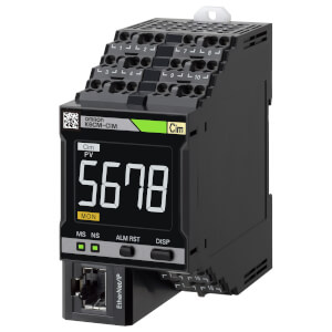
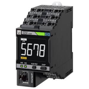
K6CM-ISM
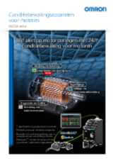
Statusbewakingsapparaat voor motoren – isolatiebewaking
De K6CM-ISM bewaakt de isolatieweerstand als indicator van de bedrading en de veiligheidsstatus van de motor.
Zodra de gemeten waarde onder de vooraf ingestelde waarschuwings- of alarmwaarde daalt, activeert het systeem de uitgang.
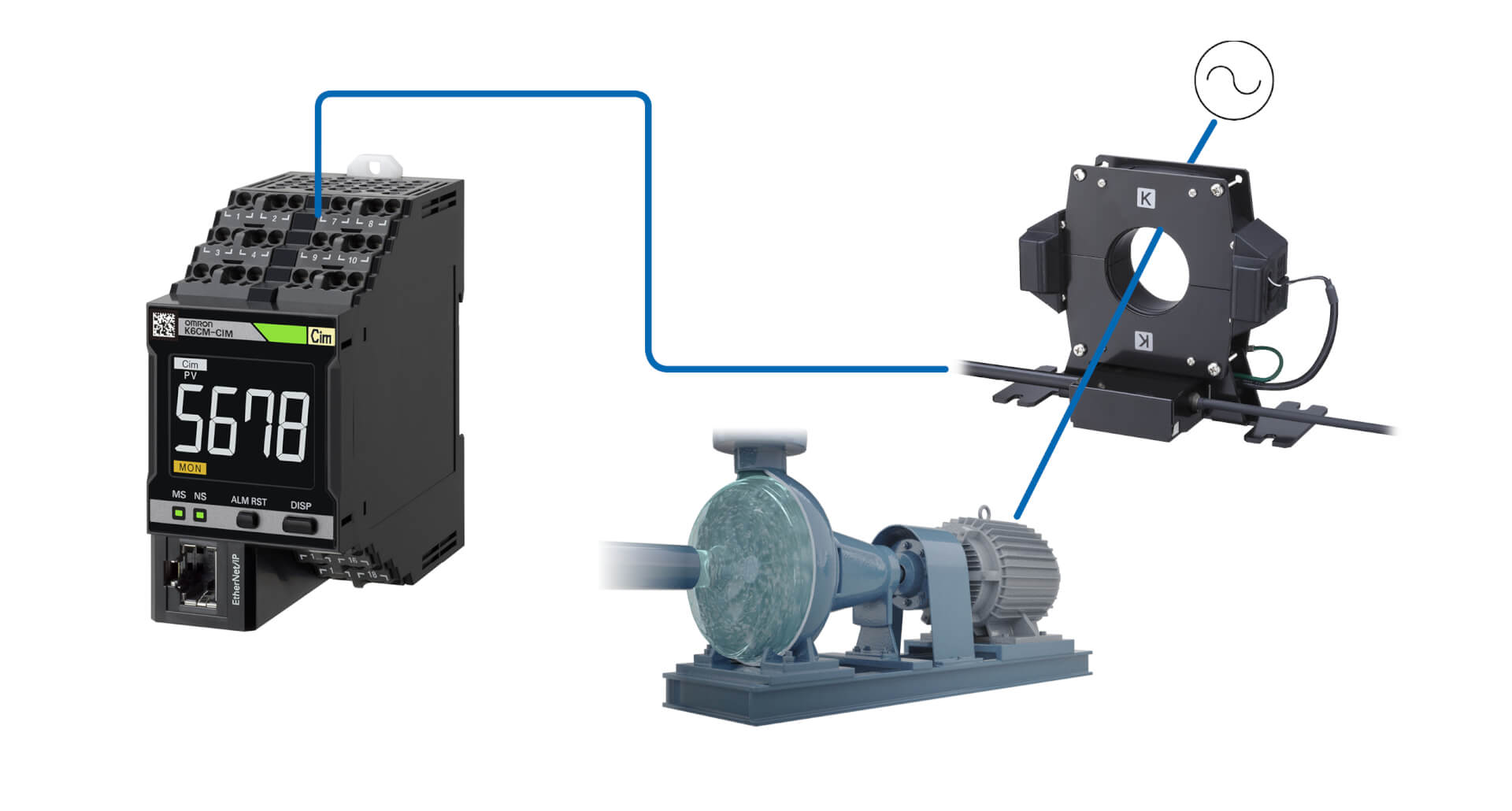
Installatie in zowel bestaande als nieuwe machines is heel eenvoudig omdat er geen sensoren op de motor hoeven te worden aangesloten: het klemtype ZCT kan eenvoudig worden geïnstalleerd op de kabels die de motor van stroom voorzien en de controller is ontworpen om in het paneel te worden geplaatst.
Het apparaat kan zelfstandig worden gebruikt of worden geïntegreerd in een bredere oplossing en maakt de volgende functies mogelijk:
- meldingen in geval van een waarschuwing of alarm;
- bewaking op afstand;
- interactie met aangepaste toepassingen en MQTT-server.
Specificaties & bestelinfo
| Product | Supply voltage AC | Supply voltage DC | Beschrijving | |
|---|---|---|---|---|
|
|
100-240 V | Motor Condition Monitoring, AC, 3-phase, Induction motor, Insulation resistance model, 100 to 240 VAC, Transistor control output, Push-in Plus, LCD display, Ethernet IP |
|
|
|
|
20.4-26.4 V | 20.4-26.4 V | Conditiebewaking voor motoren, AC, 3-fasen, inductiemotor, isolatieweerstandmodel, 24 VAC/VDC, transistor uitgang, Push-in Plus, LCD-scherm, Ethernet IP |
|
Hulp nodig?
Wij zijn er om u te helpen! Neem contact met ons op en onze specialisten helpen u bij het vinden van de beste oplossing voor uw bedrijf.
Neem contact met mij op K6CM-ISM

Dank u wel voor het insturen van uw verzoek. Wij informeren u zo snel als mogelijk.
Wij ondervinden technische problemen. Uw formulierinzending is niet gelukt. Onze verontschuldigingen hiervoor, probeer het later nog een keer. Details: [details]
DownloadOfferte voor K6CM-ISM
Met dit formulier kunt u een prijsaanvraag doen voor de producten van uw keuze. Vul alstublieft alle velden in die gemarkeerd zijn met *. Uw persoonlijke gegevens behandelen wij uiteraard volstrekt vertrouwelijk.
Dank u wel voor uw aanvraag. Wij zenden u de gewenste informatie zo snel als mogelijk.
Wij ondervinden technische problemen. Uw formulierinzending is niet gelukt. Onze verontschuldigingen hiervoor, probeer het later nog een keer. Details: [details]
DownloadFeature
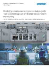
De K6CM-ISM bewaakt de isolatiestatus van een motor en waarschuwt wanneer veranderingen in de uitgangssituatie naar verwachting tot ernstige problemen zullen leiden, zodat onderhoudsingrepen goed kunnen worden gepland.
Conditiebewakingsapparaten kunnen met één tool worden geconfigureerd
Eenvoudige configuratie in drie stappen Met de configuratietool voor conditiebewaking kan een breed scala aan conditiebewakingsapparaten in batches worden geconfigureerd, zoals apparaten voor het monitoren van motoren, temperaturen, isolatie en verwarmingen. De tool kan zonder speciale vaardigheden worden gebruikt, waardoor minder training nodig is
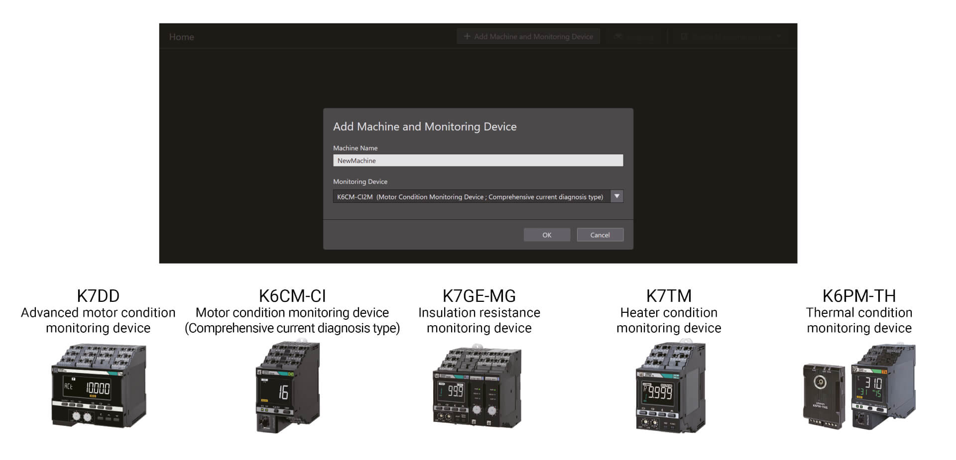
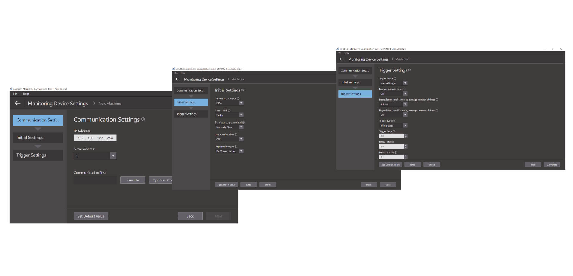
Eenvoudige configuratie in drie stappen
Met de configuratietool voor conditiebewaking kan een breed scala aan conditiebewakingsapparaten in batches worden geconfigureerd, zoals apparaten voor het monitoren van motoren, temperaturen, isolatie en verwarmingen. De tool kan zonder speciale vaardigheden worden gebruikt, waardoor minder training nodig is. De installatie kan in slechts drie stappen worden voltooid: communicatie instellen, eerste instelling en triggerinstelling.*1 Dankzij de hoge bruikbaarheid, verhoogt de tool ook de productiviteit op locatie.
Video's

-
K6CM Motor Condition Monitoring Device
K6CM takes the burden of monitoring motors off maintenance engineers. Motors can be maintained in advance of failure due to deterioration. K6CM (comprehensive current diagnosis type) can consistently monitor motor conditions by observing the current waveform of the motor. Additionally, you can understand the motor's maintenance timing without depending on an engineer, because K6CM provides threshold value setting.
02:40
K6CM Motor Condition Monitoring Device
K6CM takes the burden of monitoring motors off maintenance engineers. Motors can be maintained in advance of failure due to deterioration. K6CM (comprehensive current diagnosis type) can consistently monitor motor conditions by observing the current waveform of the motor. Additionally, you can understand the motor's maintenance timing without depending on an engineer, because K6CM provides threshold value setting.
-

K6CM Demo Video
05:48
K6CM Demo Video
Oplossingen
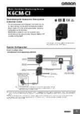
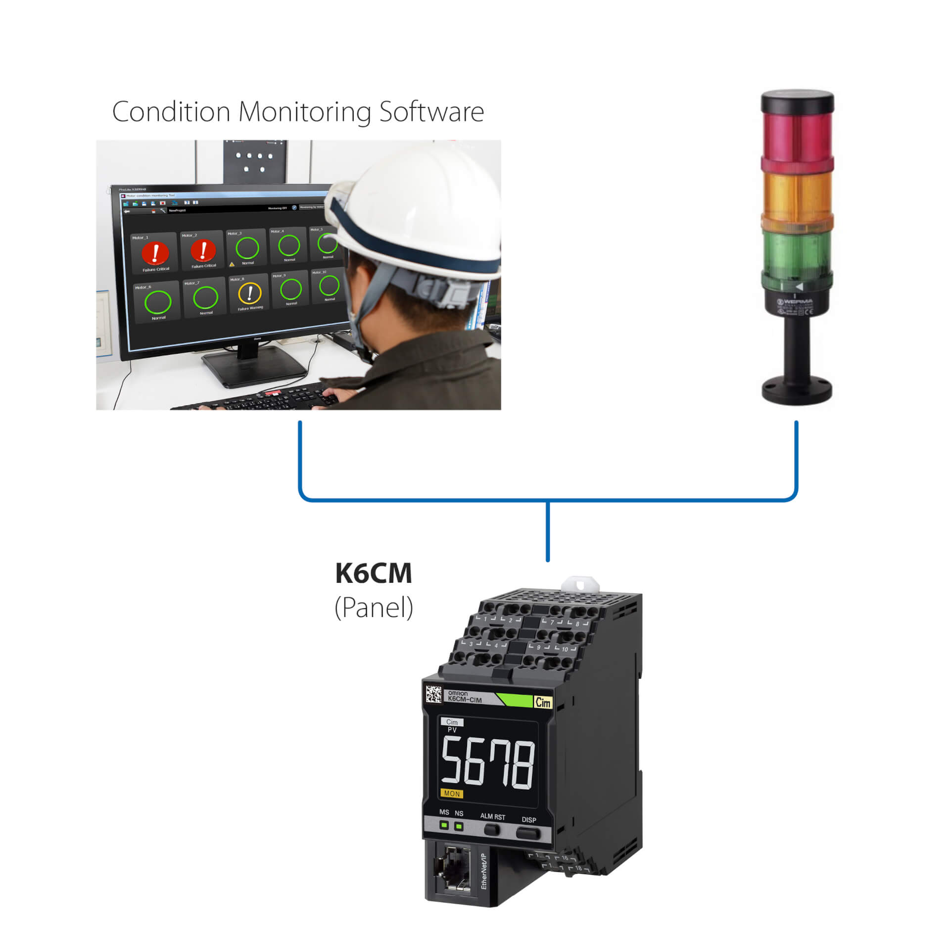
Installatie als zelfstandige oplossing (zonder PLC)
Met deze eenvoudige oplossing kunt u:
- de status van de motor bewaken via de ingebouwde LED of via de software voor statusbewaking;
- de controllers instellen via de software voor statusbewaking die bij het apparaat wordt geleverd;
- de K6CM koppelen met alle externe I/O-apparaten (dig. uitgang).
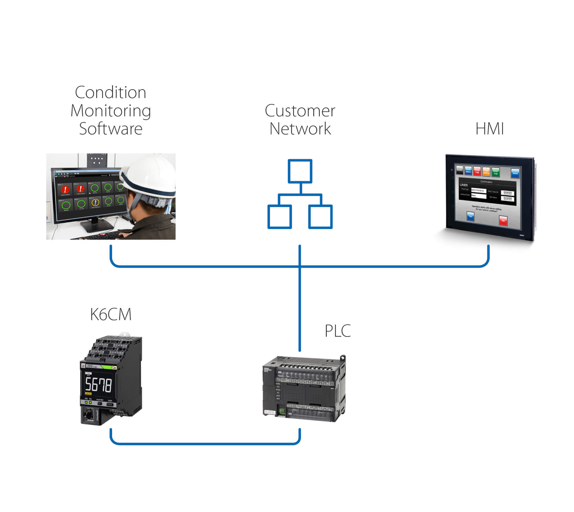
Installatie als zelfstandige oplossing (met PLC)
Deze oplossing maakt het, net als de vorige oplossing, mogelijk om:
- de status van de motor te bewaken via de software voor statusbewaking die draait op een pc die is aangesloten via een PLC;
- via de PLC acties te activeren na een waarschuwing die of alarm dat door de K6CM is gedetecteerd.
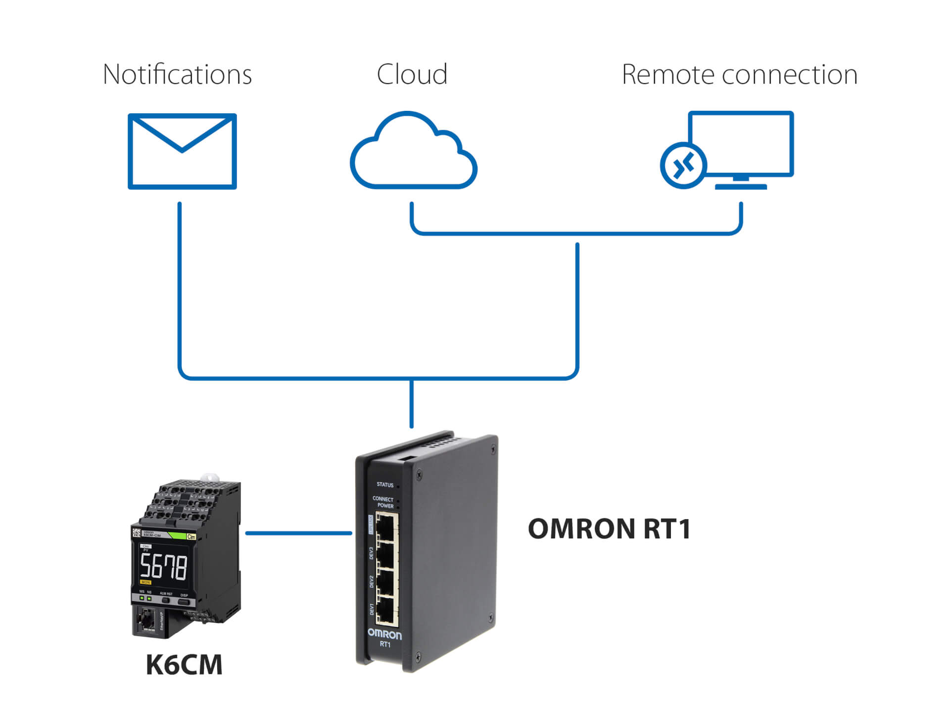
Meldingen en bewaking op afstand - zonder PLC
Deze oplossing, waarbij een RT1-unit van OMRON als gateway wordt gebruikt, maakt het volgende mogelijk:
- e-mail-/sms-meldingen als de K6CM afwijkingen detecteert;
- veilige verbinding (beheerd door de RT1) met de cloud, via LAN of via 4G-verbinding;
- veilige verbinding voor bewaking op afstand en instelling van de K6CM met behulp van de bij de controller geleverde software voor statusbewaking.
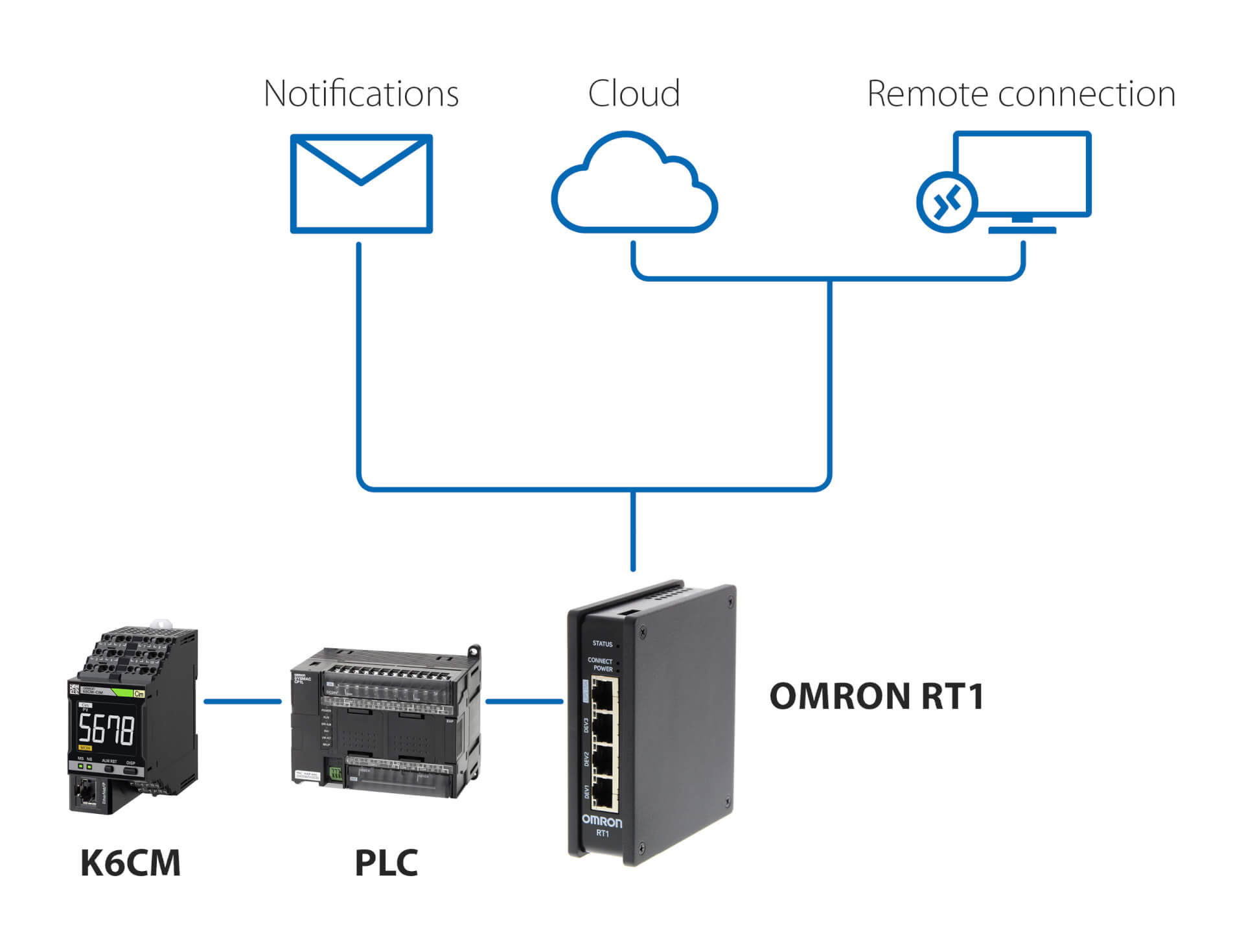
Meldingen en bewaking op afstand – met PLC
Deze oplossing, waarbij een PLC en de RT1-unit van OMRON als gateway worden gebruikt, maakt het volgende mogelijk:
- e-mail-/sms-meldingen als de K6CM afwijkingen detecteert;
- veilige verbinding (beheerd door de RT1) met de cloud, via LAN of via 4G-verbinding;
- veilige verbinding voor bewaking op afstand en instelling van de K6CM met behulp van de bij de controller geleverde software voor statusbewaking.
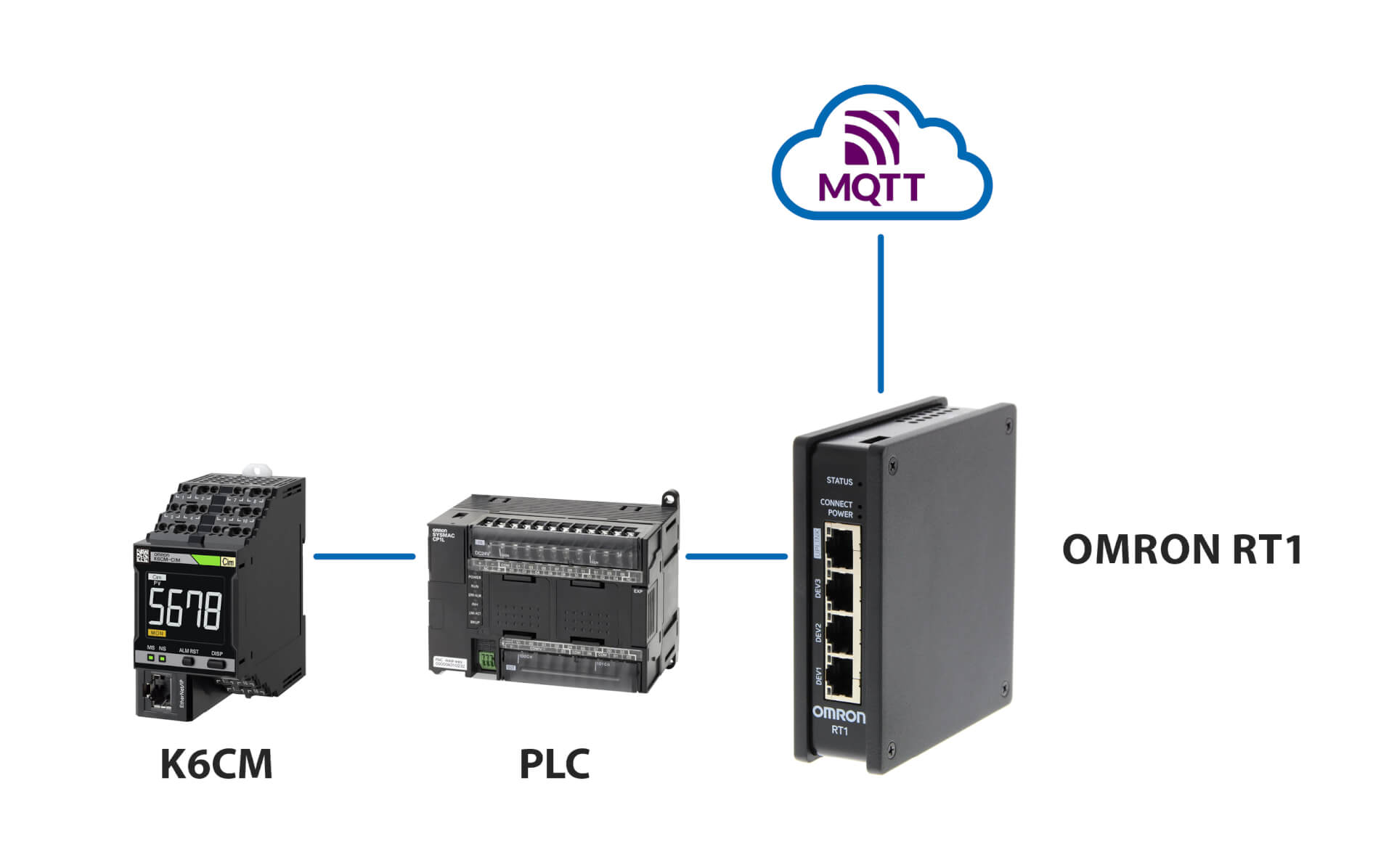
Aansluiting op MQTT-server
Verwante producten
-
Statusbewakingsapparaat voor motoren – stroombewaking
-
Statusbewakingsapparaat voor motoren – trillingsbewaking
-
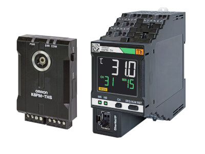
Statusbewaking op basis van thermografie
-
Statusbewakingsapparaat – isolatiebewaking
Downloads