MY
Universeel karakter maakt productfamilie geschikt voor verschillende omgevingen en toepassingen
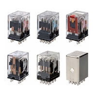
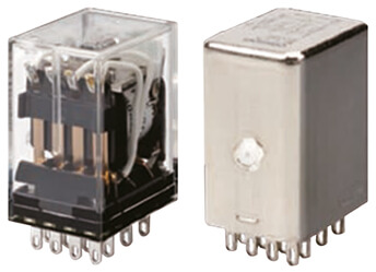
- Producten van de MY-familie hebben standaard functies op alle modellen* zoals een transparante afdekking en een mechanische indicator om de status van de contacten en de LED eenvoudig te controleren. Dit is niet alleen handig om de juiste werking van het relais te controleren, maar ook om onmiddellijk het type spoelspanning te identificeren: een rode LED voor AC-spoel en groene LED voor DC-spoel
- 2,6 mm brede pennen die zorgen voor een hogere geleidbaarheid en een geringere temperatuurstijging
- MY-GS-R is het vlaggenschip van de productfamilie met 2- en 4-polige modellen die beschikbaar zijn met LED, testknop en bescherming. De DC-uitvoering heeft dankzij het LED-ontwerp geen polariteit (met uitzondering van modellen met diode).
- Beschikbare hermetisch of met kunststof afgedichte relais, modellen met vorkvormige vergulde contacten voor zeer kleine belastingen
- De bedradingstijd kan worden ingekort met maar liefst 60%** vergeleken met conventionele schroefaansluitingen. Door de MY te combineren met de Push-in Plus-aansluitingen (PYF-[]-PU) wordt de bedradingstijd ingekort omdat slechts lichte insteekkracht moet worden gebruikt.
* Speciale modellen zijn uitgesloten
** Wanneer zowel Push-in Plus-aansluitingen als schroefaansluitingen worden gecombineerd met insteekklemmen
Stopzetting product: maart 2024 is ALLEEN van toepassing voor EUROPA. Download dit stopzettingsbericht voor meer informatie.
Specificaties & bestelinfo
| Product | Mounting method | Usage | Poles | Rated carry current | Coil voltage | Operation voltage | Contact material | Contact description | Features | Terminal type | Beschrijving | |
|---|---|---|---|---|---|---|---|---|---|---|---|---|
|
|
With plug-in socket | General purpose | 2 | 10 A | 110 V | AC | Ag | DPDT | Transparent case, With mechanical indicator | Plug-in, Solder | Relais, plug-in, 8-polig, DPDT, 7 A, mechanische indicator, 110/120 VAC |
|
|
|
With plug-in socket | General purpose | 2 | 10 A | 12 V | AC | Ag | DPDT | Transparent case, With mechanical indicator | Plug-in, Solder | Relais, plug-in, 8-polig, DPDT, 7 A, mechanische indicator, 12 VDC |
|
|
|
With plug-in socket | General purpose | 2 | 10 A | 230 V | AC | Ag | DPDT | Transparent case, With mechanical indicator | Plug-in, Solder | Relais, plug-in, 8-polig, DPDT, 7 A, mechanische indicator, 220/240 VAC |
|
|
|
With plug-in socket | General purpose | 2 | 10 A | 24 V | AC | Ag | DPDT | Transparent case, With mechanical indicator | Plug-in, Solder | Relais, plug-in, 8-polig, DPDT, 7 A, mechanische indicator, 24 VAC |
|
|
|
With plug-in socket | General purpose | 2 | 10 A | 48 V | AC | Ag | DPDT | Transparent case, With mechanical indicator | Plug-in, Solder | Relais, plug-in, 8-pins, DPDT, 10 A, mechanische indicator, 48 VAC |
|
|
|
With plug-in socket | General purpose | 2 | 10 A | 110 V | DC | Ag | DPDT | Transparent case, With mechanical indicator | Plug-in, Solder | Relais, plug-in, 8-polig, DPDT, 7 A, mechanische indicator, 100/110 VDC |
|
|
|
With plug-in socket | General purpose | 2 | 10 A | 12 V | DC | Ag | DPDT | Transparent case, With mechanical indicator | Plug-in, Solder | Relais, plug-in, 8-polig, DPDT, 10 A, mechanische indicator, 12 VDC |
|
|
|
With plug-in socket | General purpose | 2 | 10 A | 24 V | DC | Ag | DPDT | Transparent case, With mechanical indicator | Plug-in, Solder | Relais, plug-in, 8-polig, DPDT, 7 A, mechanische indicator, 24 VDC |
|
|
|
With plug-in socket | General purpose | 2 | 10 A | 48 V | DC | Ag | DPDT | Transparent case, With mechanical indicator | Plug-in, Solder | Relais, plug-in, 8-pins, DPDT, 10 A, mechanische indicator, 48 VDC |
|
|
|
With plug-in socket | General purpose | 2 | 10 A | 110 V | AC | Ag | DPDT | CR circuit, LED, Test button, Transparent case, With mechanical indicator | Plug-in, Solder | Relais, plug-in, 8-pins, DPDT, 10 A, mechanische en LED-indicatoren, spoelspanningsabsorptie, vergrendelbare druktestknop, 110/120 VAC |
|
|
|
With plug-in socket | General purpose | 2 | 10 A | 230 V | AC | Ag | DPDT | CR circuit, LED, Test button, Transparent case, With mechanical indicator | Plug-in, Solder | Relais, plug-in, 8-pins, DPDT, 10 A, mechanische & LED-indicatoren, Coil Surge Absorption, vergrendelbare druktestknop, 220/240 VAC |
|
|
|
With plug-in socket | General purpose | 2 | 10 A | 24 V | DC | Ag | DPDT | Diode, LED, Test button, Transparent case, With mechanical indicator | Plug-in | Relais, plug-in, 8-polig, DPDT, 10 A, mechanische en LED-indicatoren, met ingebouwde diode voor absorptie van spoelspanningspieken, omgekeerde polariteit, vergrendelbare testdrukknop, 24 VDC |
|
|
|
With plug-in socket | General purpose | 2 | 10 A | 110 V | DC | Ag | DPDT | Diode, LED, Test button, Transparent case, With mechanical indicator | Plug-in, Solder | Relais, plug-in, 8-pins, DPDT, 10 A, mechanische & LED indicatoren, Coil Surge Absorption, vergrendelbare druktestknop, 100/110 VDC |
|
|
|
With plug-in socket | General purpose | 2 | 10 A | 12 V | DC | Ag | DPDT | Diode, LED, Test button, Transparent case, With mechanical indicator | Plug-in, Solder | Relais, plug-in, 8-pins, DPDT, 10 A, mechanische & LED indicatoren, Coil Surge Absorption, vergrendelbare druktestknop, 12 VDC |
|
|
|
With plug-in socket | General purpose | 2 | 10 A | 24 V | DC | Ag | DPDT | Diode, LED, Test button, Transparent case, With mechanical indicator | Plug-in, Solder | Relais, plug-in, 8-polig, DPDT, 10 A, mechanische en LED-indicatoren, diode, vergrendelbare testdrukknop, 24 VDC |
|
|
|
With plug-in socket | General purpose | 2 | 10 A | 110 V | AC | Ag | DPDT | LED, Test button, Transparent case, With mechanical indicator | Plug-in, Solder | Relais, plug-in, 8-polig, DPDT, 10 A, mechanische en LED-indicatoren, vergrendelbare testdrukknop, 110/120 VAC |
|
|
|
With plug-in socket | General purpose | 2 | 10 A | 12 V | AC | Ag | DPDT | LED, Test button, Transparent case, With mechanical indicator | Plug-in, Solder | Relais, plug-in, 8-polig, DPDT, 10 A, mechanische en LED-indicatoren, vergrendelbare testdrukknop, 12 VAC |
|
|
|
With plug-in socket | General purpose | 2 | 10 A | 230 V | AC | Ag | DPDT | LED, Test button, Transparent case, With mechanical indicator | Plug-in, Solder | Relais, plug-in, 8-polig, DPDT, 10 A, mechanische & LED-indicatoren, vergrendelbare testdrukknop, 220/240 VAC |
|
|
|
With plug-in socket | General purpose | 2 | 10 A | 24 V | AC | Ag | DPDT | LED, Test button, Transparent case, With mechanical indicator | Plug-in, Solder | Relais, plug-in, 8-polig, DPDT, 10 A, mechanische en LED-indicatoren, vergrendelbare testdrukknop, 24 VAC |
|
|
|
With plug-in socket | General purpose | 2 | 10 A | 48 V | AC | Ag | DPDT | LED, Test button, Transparent case, With mechanical indicator | Plug-in, Solder | Relais, plug-in, 8-pins, DPDT, 10 A, mechanische & LED-indicatoren, vergrendelbare druktestknop, 48 VAC |
|
Hulp nodig?
Wij zijn er om u te helpen! Neem contact met ons op en onze specialisten helpen u bij het vinden van de beste oplossing voor uw bedrijf.
Neem contact met mij op MY

Dank u wel voor het insturen van uw verzoek. Wij informeren u zo snel als mogelijk.
Wij ondervinden technische problemen. Uw formulierinzending is niet gelukt. Onze verontschuldigingen hiervoor, probeer het later nog een keer. Details: [details]
Offerte voor MY
Met dit formulier kunt u een prijsaanvraag doen voor de producten van uw keuze. Vul alstublieft alle velden in die gemarkeerd zijn met *. Uw persoonlijke gegevens behandelen wij uiteraard volstrekt vertrouwelijk.
Dank u wel voor uw aanvraag. Wij zenden u de gewenste informatie zo snel als mogelijk.
Wij ondervinden technische problemen. Uw formulierinzending is niet gelukt. Onze verontschuldigingen hiervoor, probeer het later nog een keer. Details: [details]
Modellen
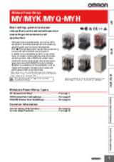
MY-GS-R - Miniature Power Relays Mechanical indicators added as a standard feature to our best-selling MY General-purpose relays
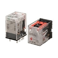
- MY-GS-R is de nieuwste toevoeging aan de MY-familie: geproduceerd in een volledig geautomatiseerde fabriek
- Vermindert de bedradingstijd met 60% wanneer het wordt gecombineerd met de PYF-PU Push-in Plus-aansluitingen (volgens de feitelijke Omron-metingen).
- Op de spoeltape is de bedrijfsspecificatie van de spoel aangegeven
- Mechanische bedrijfsindicatoren zijn standaard aanwezig op alle modellen
- Voldoet aan RoHS, UL, CSA en IEC (VDE-certificering).
- Mechanische indicatoren zijn standaard op alle modellen om de contactstatus eenvoudig te controleren.
- MY-GS-R is geschikt voor toepassingen waarbij een betrouwbaar relais nodig is. Het standaardmodel wordt vaak gebruikt in verpakkingsmachines voor de voedingsmiddelen- en drankenindustrie
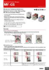
MY(S) - Miniature Power Relays
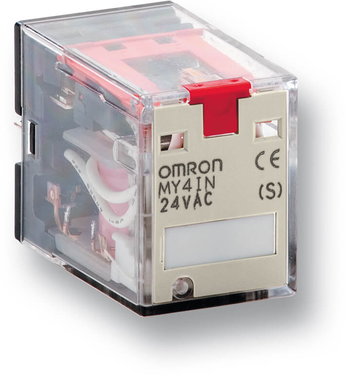
Veelzijdig insteekrelais dat de norm vaststelt
- Sinds de introductie van dit mini-voedingsrelais zijn er meer dan 1 miljard van gemaakt en zijn ze met succes gebruikt in veel verschillende toepassingen. Vorkvormige contacten zijn optioneel leverbaar voor een betrouwbare schakeling met lage stroom gedurende de gehele elektrische levensduur. Er is een volledig assortiment aansluitingen beschikbaar voor montage met schroef-, klem- en schroefloze klemmethode.
- De MY-S-modellen met LED- en testknop zijn het meest verkochte product dankzij de zichtbare indicator en de gebruiksvriendelijke testfunctie
- De MY-S-serie omvat MY4Z-modellen met vorkvormige contacten voor zeer kleine belastingen
- MY-S wordt veel gebruikt in de gebouwautomatisering en wordt vaak door de klant gekozen als voorkeursrelais voor klimaatregelingstoepassingen/HVAC en liftsystemen
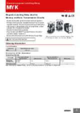
MYK - Miniature Power Latching Relays
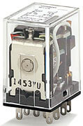
Magnetisch vergrendelrelais, ideaal voor geheugen- en gegevensoverdrachtscircuits
- MYK magnetische vergrendelingsrelais die de status van de contacten behouden en een laag energieverbruik hebben
- Vergrendelsysteem met dubbele wikkeling dat restmagnetisme vasthoudt. De speciale magnetische materialen maken veranderingen door veroudering verwaarloosbaar, waardoor een lange continue houdtijd wordt gewaarborgd. Er is weinig verandering in kenmerken zoals het volgen van contacten, contactdruk, enz. gedurende de lange levensduur.
- Bijzonder trilling-/schokbestendig
- Ingebouwde bedrijfsindicator zorgt voor gemakkelijke bewaking AAN/UIT-schakeling
- MY2K wordt ook gebruikt in panelen die speciaal zijn bedoeld voor windenergietoepassing
MYQ/MYH - Miniature Power Sealed Relays
Afgedichte relais die goed bestand zijn tegen omgevingen waar stof of corrosieve gassen, etc. aanwezig zijn
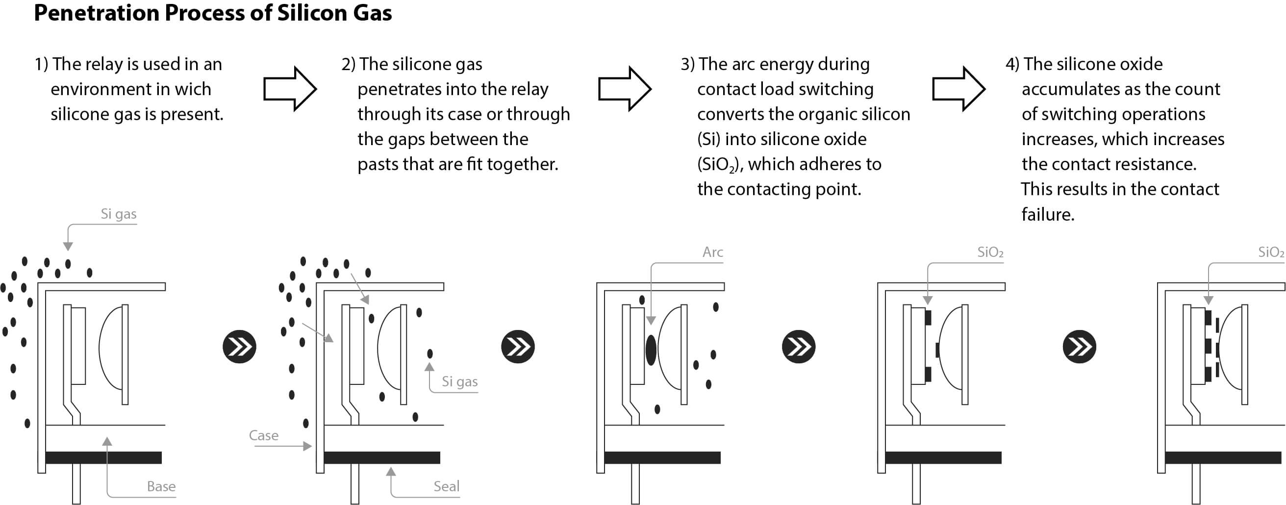
- In stofproducerende omgevingen, bijvoorbeeld bij spuitgietmachines en slijpmachines en in toepassingsomgevingen waarin kleine insecten (zoals muggen) aanwezig zijn, kunnen deze vreemde stoffen in het relais doordringen, door openingen tussen onderdelen van het relais en via de ventilatiegaten van het relais. Eenmaal in het relais blijven stof en insecten vaak in het relais vastzitten. Als ze zich aan de contacten hechten, kan dit problemen opleveren zoals contactstoring en onstabiele contacten. Kunststof afgedichte relais (MYQ) en hermetisch afgedichte relais (MYH) zijn bestand tegen invloeden van de omgeving
- Ook aanbevolen voor omgevingen waar corrosieve gassen zoals chloor, zwavelzuur en siliconengas worden gegenereerd
- Ze zijn ook bestand tegen omgevingen waar zoutschade optreedt en waar stof wordt gegenereerd.
- Storingen in relaiscontacten worden voorkomen door een uiterst luchtdichte structuur
Video's

-

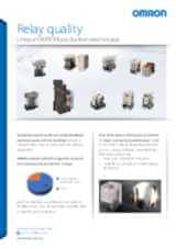
OMRON Relay Quality
Creating the perfect relays may seem like a straightforward task, but it’s a complex process that requires the most advanced manufacturing processes. This ensures that every component inside our relays are precisely assembled and protected from any outside contaminants. Ignoring this crucial step could jeopardize the reliability of the relays and compromise their switching activity. At times, machines can experience unplanned downtime, with the causes remaining elusive, in many cases restarting the machine or replacing the relays resolves the issue. OMRON determined that such incidents are primarily caused by inadequate contact conduction, which frequently results from dust caught between the contacts during manufacturing. OMRON's unique production techniques avoid poor conduction due to dust by providing standardized product design, producing the products in clean room with strict entry/exit control rules, and utilizing OMRON’s unique dust removal technology. This production technique are applied for all the OMRON relays especially the new ones introduced in the line up G2RV-ST/G3RV-ST, and MY-GS-R. Find out more about our new relays in our website: #MakeitOMRON #MakeitExcellent
02:30
OMRON Relay Quality
Creating the perfect relays may seem like a straightforward task, but it’s a complex process that requires the most advanced manufacturing processes. This ensures that every component inside our relays are precisely assembled and protected from any outside contaminants. Ignoring this crucial step could jeopardize the reliability of the relays and compromise their switching activity. At times, machines can experience unplanned downtime, with the causes remaining elusive, in many cases restarting the machine or replacing the relays resolves the issue. OMRON determined that such incidents are primarily caused by inadequate contact conduction, which frequently results from dust caught between the contacts during manufacturing. OMRON's unique production techniques avoid poor conduction due to dust by providing standardized product design, producing the products in clean room with strict entry/exit control rules, and utilizing OMRON’s unique dust removal technology. This production technique are applied for all the OMRON relays especially the new ones introduced in the line up G2RV-ST/G3RV-ST, and MY-GS-R. Find out more about our new relays in our website: #MakeitOMRON #MakeitExcellentVerwante producten
-
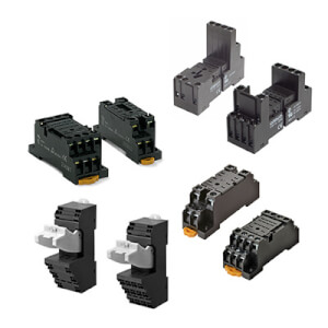
PYF is de reeks aansluitvoeten voor de MY-serie relais, ook geschikt voor solid-state relais (SSR) en timers
Downloads
_miniature_power_relays_datasheet_en.jpg)
_series_(europe)_discontinuation_notice_en.jpg)
_discontinuation_notice_en.jpg)
_myk_myq_myh_miniature_power_relays_datasheet_en.jpg)
n1-d2_and_my4(i)n1-d2_discontinuation_notice_en.jpg)